4.8 COMBUSTION INSTABILITY
"Combustion instability" is defined in terms of amplitude of pressure fluctuations in the combustion chamber. Chamber-pressure fluctuations are always present during normal, stable operation of a rocket engine system. These fluctuations are generally quite random, showing frequency spectra which are essentially continuous in nature, with few, if any, recognizable peaks. However, in case of instability, large concentrations of vibratory energy appear at one or more frequencies in the spectrum. They can easily be recognized against the normal random-noise background.
It has been found experimentally that the amplitude of the chamber pressure oscillations which will cause detrimental physical or operational effects varies widely for different thrust chambers and engine systems. Also, in a given chamber or system the effects of various types of instability can be quite different at the same amplitude. Thus it is difficult to assign a quantitative value to the amplitude at which the combustion chamber should be considered as running unstable.
It is an interesting observation that the first large liquid-propellant rocket-propulsion system, the German A-4 (V-2) rocket, never experienced combustion instability in over 4000 launchings and in several times as many static chamber and engine firings. The term "combustion instability" was literally unknown. It has been suggested that the Germans may have had instability, but did not know it because of their poor high-speed recorders. To this it can be said that for those instabilities which have caused today's real difficulties, the high-speed recorder chart is merely a postmortem confirmation of the cause of often very costly failures, which did not require any special instrumentation but were unmistakable even to the untrained visual observer. It is much more likely that there is a relationship between the low performance level of the A-4 or the chamber geometry, or both, and the inherent stability.
Experimentally it has been found that as long as the ratio of the peak-to-peak amplitude of pressure oscillation to average chamber pressure is kept below 0.10 , there is usually no physical damage to the chamber. However, while a percent variation in pressure for any class of instability may not appear to have detrimental physical effects instantly or within a short period, it would be unacceptable for longer range rocket vehicle missions. One practical way to detect combustion instability and to prevent it from causing damage during engine operation is by monitoring the vibratory acceleration of the system. Accelerometers are mounted on the system to monitor in all three coordinates. They are connected to discriminator circuits which are set to specific g-load limits. When these limits are exceeded, a counting instrument begins to record. As soon as an allowable cumulative number of oscillations is exceeded, an engine cutoff signal is automatically triggered to prevent damage.
Types of Instability
For proper remedial action, it will often be important to know whether the observed oscillations are of a longitudinal, radial, or tangential mode, or a combination of these. These three modes and their normal acoustic frequency are indicated in figure 4-59. Furthermore, in certain cases, it will be extremely valuable to know whether the oscillations originated in the thrust chamber, or in the feed system, or whether they originate in an interaction of characteristics. harmless when separate but destructive when
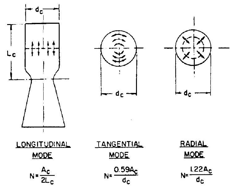 Figure 4-59.-Three modes of instability. combustion chamber length (injector face to throat); combustion chamber diameter; normal acoustic frequency; velocity of sound in chamber.
combined, of both feed system and chamber. This will be further discussed in connection with methods to improve stability.
The effects of the oscillations on an engine system are very much dependent on frequency. These effects may range from simple shaking (usually at the lower frequencies), possibly resulting in an eventual mechanical failure after sometimes prolonged exposure, to "acoustic" vibrations (usually at the higher frequencies) capable of destroying the entire system in a few hundred milliseconds. But, how low is "low" and how high is "high"? As pointed out earlier, the general field of combustion stability is extremely complex and it would be far beyond the scope of this book to attempt to present a generalized theory of the subject. Each system, because of configuration and dimensions, behaves somewhat differently and requires special treatment. The thrust chamber designer must have a basic understanding of the stability problem, and it is felt that this can best be conveyed by describing it in terms of a typical system, for which a substantial amount of experimental data exists.
The frequency of the chamber pressure oscillations in a given chamber is determined by the geometry of the system as well as by complex interactions between the fluid flow in the propellant lines, the physical and chemical process
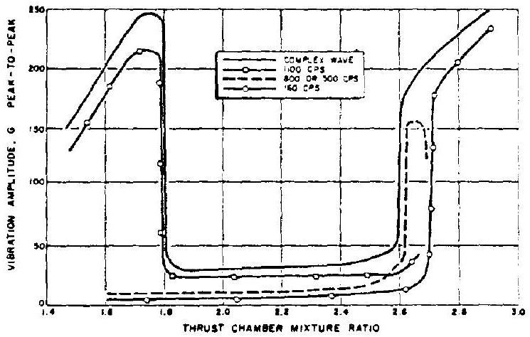 Figure 4-60.-Approximate vibration characteristics at 150000 lb thrust level.
of combustion, and the dynamics of the combustion gases in the chamber. It has been found that each of the frequency components in the instability spectrum of a thrust chamber is predominantly influenced by only one physical process so that it is possible to group the observed instabilities in broad general classes, which are: high frequency or gas dynamics, low frequency or hydrodynamics, and intermediate frequency or combustion dynamics, listed in the order of their relative importance. Figure 4-60 presents vibration amplitudes of various frequencies versus mixture ratio of a typical RP-1 engine at the 150000 -pound thrust level. The graph indicates the large difference in vibration amplitude between a stable and an unstable region.
High-Frequency Instabilities
High-frequency instabilities at frequencies of approximately 1000 cps and over are sometimes referred to as "damaging acoustic," or "screaming" modes of instability. They are gas-dynamic instabilities which are both sustained and initiated by the combustion process and are believed to be concentrated in the uppermost portion of the combustion chamber where they cause increased heat-transfer rates to the injector sufficient to melt and burn it through within a few hundred milliseconds. They also frequently have serious damaging effects upon other parts of the rocket engine system. High-frequency instabilities are further characterized by instantaneous initiation (a few milliseconds from absence to full amplitude), and by extreme difficulty in eliminating them once they are initiated. They do not occur at, nor can they be generally damped to, low-amplitude levels. They are either present at high amplitudes or not at all. It is believed that these oscillations are predominantly of the radial and tangential types.
In many systems extremely unpredictable high-frequency instability has occurred. It is often, but by no means always, connected with the buildup phase to main stage. Systems which ran stably during numerous successive tests can become unstable without warning or subsequent clear indication of a cause. Figure 4-61 shows the starting of a typical high-frequency instability, indicated by the sudden shift in the accelerometer trace due to high-amplitude chamber pressure oscillations. All types of rocket propulsion systems, including solid systems, have been plagued by high-frequency instability. A considerable amount of research and engineering has been devoted to the explanation and elimination of this phenomenon.
Unless a run in which instability is encountered is terminated within fractions of a second, serious damage to the engine hardware almost always occurs. It is assumed that the rapid gas pulsations directly interface with propellant injection, their mixing, and with the combustion process, upsetting the condition in the boundary zones, in particular at the injector face, to such an extent that the heat transfer to the metal parts increases at a high rate. Within seconds, or even fractions thereof, the injector can burn through, permitting propellant mixing behind the injector face. This, in turn, leads to explosions which often completely destroy the system.
It has been observed that the degree and speed of damage is somewhat related to the level of energy release occurring in the combustion chamber. This may explain why "bursts of
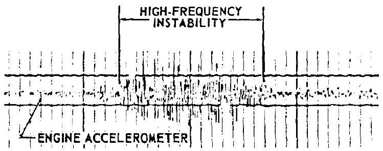 Figure 4-61. -High frequency combustion instability shown on oscillograph for engine accelerometer.
instability" during shutdown cause damage less frequently than they do during buildup and main stage.
Low-Frequency Instabilities
This type of instability, at frequencies below approximately 180 cps , is a hydrodynamic oscillation, characterized by a cause-and-effect-type coupling between combustion process and propellant feed system flow processes. The phenomenon is sometimes referred to as "chugging." Its secondary effects can be serious indeed. "Chugging" may trigger destructive high-frequency instability. Also, prolonged chugging can lead to loosening of bolts and other vital connections and to ruptures in general. Low-frequency instability is self-sustaining but may damp out. As a rule, it is predictable from analytical and from test result studies. In figure the high-speed-pressure instrumentation measurements indicating chugging clearly show that the oscillations of propellant feed system pressures are at the same frequency as the "rough combustion cutoff accelerometer" reading.
Chugging occurs most frequently during buildup and shutdown of an engine system, or when operating at off-rated operating levels, such as at incorrect mixture-ratio values. Likewise, too high, and particularly, too low a thrust level can lead to chugging. This is especially important for systems requiring throttling to a lower-than-rated thrust level during flight. If sustained, chugging will cause measurable performance losses, which are attributable to widely fluctuating mixture ratios.
The chugging phenomenon is frequently associated with the quality and promptness of ignition of the entering propellants. This can be described as "flame holding characteristics," "combustion timelags," "flame propagation velocity," or other terms, which ultimately are all traceable to the excessive accumulation of unburned fuel, with subsequent detonation or cyclic higher-than-rated combustion. The resulting excessive chamber-pressure spikes effect a reduction, or even reversal, of the propellant flows. This will cause rapid collapse of the chamber pressure, allowing propellants to rush in again, thus repeating the cycle. It is readily evident that the physical dimensions of the com-
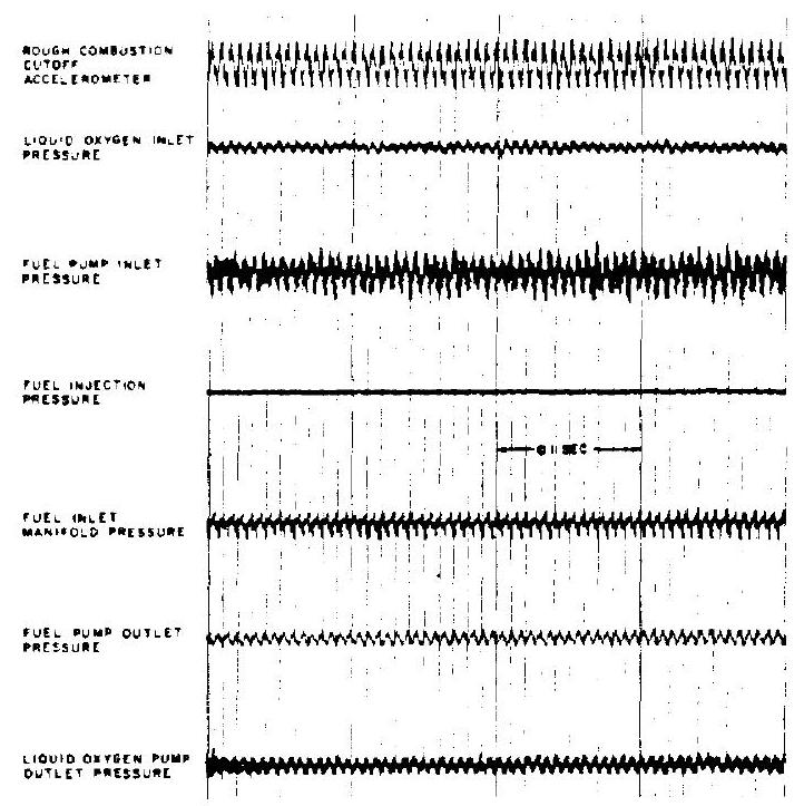 Figure 4-62.-High-speed pressure measurements of low-frequency instability.
bustion chamber and of the propellant ducts, and the magnitude of the propellant flow rates and their ratio to one another (in a bipropellant system), are critical to the phenomenon of lowfrequency system oscillations.
Intermediate-Frequency Instabilities
This instability, with frequencies ranging from 200 to 1000 cps , is sometimes referred to as combustion dynamics or "buzzing." It is characterized by a spring-and-mass-type coupling between combustion process and propellant feed system flow processes. It is often present in only a portion of the feed system, or is confined to the combustion chamber, or, in a bipropellant system, to one of the two propellant systems only. It appears to be initiated by the combustion process and to be sustained by acoustic resonance of a critical portion of the system. Some researchers have shown that in a system having a pump, the pump may be the prime source of these oscillations.
This type of instability has not appeared to be a problem in the development of large engines. While it can occur occasionally in large engines, it appears to be much more prevalent in smallscale low-thrust systems. Systems oscillations of the buzzing type are undesirable because of their adverse effects on engine reliability and
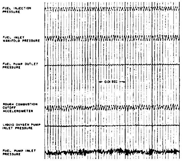 Figure 4-63.-High-speed pressure measurements of intermediate frequency instability.
performance. When exposed to prolonged buzzing, critical parts of the engine may fail because of material fatigue, and thus cause secondary major failures. In addition, measurements have shown that a performance ( ) loss of up to approximately 7 percent can be incurred, which is largely attributed to widely fluctuating mixture ratios.
Figure 4-63 is the record of high-speed-pressure measurements of a typical test afflicted by buzzing. The oscillation is attenuated in the fuel pump outlet pressure, and nonexistent in the pump inlet pressure. This indicates that the buzzing is limited to only a part of the feed system.
Field of Stability
For a given engine system, combustion stability limits can be defined experimentally in terms of certain operational parameters such as chamber pressure, injection , and mixture ratio. Figure 4-64 presents the stability field for a typical -pound nominal thrust engine system. The stability field, together with heat transfer limits, can serve as a guide to the design of a safely operating engine system.
Design Approaches Toward Control of Combustion Instability
The problem of controlling combustion insta-
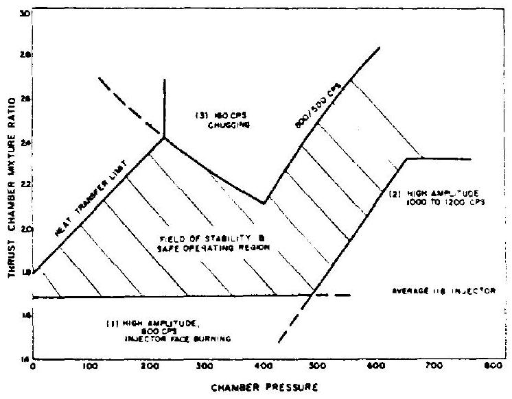 Figure 4-64.-Field of stability and safe operating region of a typical engine system.
bility in liquid propellant rocket engine systems can be attacked in several ways, including systems design, choice of propellant combination, and operating conditions, and through the use of special control devices. Two basic approaches toward eliminating combustion instability are employed. The first is to eliminate triggering processes and/or to limit the driving energy per cycle to a value below the damping per cycle inherent to the system. This approach is typified by design investigations in which injector configurations are varied to give different atomization and propellant distribution characteristics with varying resistance to initiation of instability, or in which propellant additives are used which modify the physical properties controlling spray formation, chemical kinetics, etc. Experimental studies, both with full-scale engines and with research model thrust chambers, have shown that injector modification yields relative stability ratings, differing by a factor from 5 to 6 from the most stable to the least stable configuration.
The second approach is to introduce additional damping in the system through the use of mechanical or other devices so that any operational disturbance, or oscillation triggered by the disturbance, are sufficiently and rapidly damped out. Experience over the past several years has shown that the destructive transverse acoustic modes of instability can be most effectively combated through the use of this second approach. Mechanical devices, such as baffles or a divergent wall gap, have been found to introduce sufficient damping into the system so that it will recover from an instability triggered by an explosive charge as large as can be used without damaging the thrust chamber in some other manner. This ability of a system to recover from a triggered instability has been designated as "dynamic stability." A prerequisite for any propulsion system to operate reliably is that it should exhibit dynamic stability with respect to all modes of instability. As a minimum requirement it should be "dynamically stable" at least with respect to the destructive transverse (radial and tangential) acoustic modes.
The successful application of the above methods has been based primarily on criteria established empirically in research model thrust chambers, together with testing in actual engine systems. However, the understanding of the fundamental physical principles of the damping processes is still limited.
Prevention of Triggering Processes
The most desirable design method of controlling instability is the prevention of those physical or chemical processes which trigger and/or sustain the resonant modes of the combustion chamber or engine system. While a great number of studies, in which different design parameters were varied systematically, have been made by various investigators, the results have failed to yield truly generalized design criteria. This can be traced to the fact that basic processes which trigger and sustain the various types of instability have not been isolated. Thus, while a parameter which controls one type of instability may have been established on an engineering basis, this same design criterion may be enhancing another type of instability. The following is a general discussion of the prevention of triggering instability in various component and subsystem designs:
- Propellant feed system design.-Past experience has indicated that certain combustion instabilities, such as buzzing, are sustained through an interaction between feed system and combustion dynamics. It is believed that hydraulic resonances are a major factor in sustaining this type of instability. The requirement is to design a feed system whose hydraulic charac- teristics will not trigger the interaction with the combustion process.
- Combustion chamber design.-Analytical studies and experimental results have indicated that the geometrical configuration of the combustion chamber will determine the type of frequency of the acoustic modes of instability. Chambers having large length-to-diameter ratios appear to be quite prone to large-amplitude longitudinal instability. On the other hand, chambers having small length-to-diameter ratios appear to be sensitive to the transverse modes. Also, smalldiameter chambers are much more stable than large-diameter chambers. The requirement is to design a chamber geometry which will have least tendency to trigger instability, in conjunction with other considerations.
- Injector design.-The injector design appears to be a most critical factor in triggering instability. In turn, it offers great potential for controlling instability-triggering processes through variation of parameters. Of the most common types of injectors, the self-impinging injector (fig. 4-45a) has been chosen by many investigators as the best compromise between performance and stability. There is some indication that longitudinal instability may be enhanced if the propellant travel time from the injector face to the point of impingement is close to the half-period (or an odd multiple of the halfperiod) of the longitudinal mode oscillations. There are strong indications that increasing the injection to too great a value may cause the thrust chamber to operate unstably in the transverse acoustic modes. The effect of injection on the longitudinal acoustic modes and on hydrodynamic instabilities appears to be just the opposite, with stability improving as increases. The propellant distribution across the injector face has a significant relation to triggering transverse modes of instability.
- Propellant combination and mixture ratio.Control tests with various propellants have shown that there are certain oxidizers of fuels which can be triggered into instability more easily than others, in general or at certain mixture ratio conditions. In systems, a lower hydrogen injection temperature tends to trigger instability.
- Engine system operating characteristics.In some cases, combustion instability can be avoided by modification of engine-system operating characteristics. For instance, if the chamber pressure buildup period during engine start is excessive, "chugging" may have time to develop. This low-frequency instability, in turn, can trigger the destructive acoustic modes of instability by contaminating one propellant system with the other propellant by driving it back through the injector ports. The triggering chugging can be eliminated through a fast chamber pressure buildup.
Application of Damping Devices
In further support of design for stability, special damping devices can be provided for "dynamic stability" in the combustion chamber and engine system. The following are several devices which have been applied with good results:
- Feed system hydraulic capacitor.-Selfsustained combustion and feed system instabilties of the buzzing type can be eliminated by introducing hydraulic capacitors in the feed system. A hydraulic capacitor is any device which will increase the effective compressibility at a given point in the liquid system. Figure 4-65 shows the schematic of an experimental hydraulic capacitor. It is an isolation-type capacitor with large capacitance and zero resistance between it and the system. Its function is to isolate the transmission of pressure disturbances through the system above a given frequency. Another type is called absorption capacitor, which has small capacitance and high resistance between it and the system. Its function is to absorb the oscillatory energy of the system by damping or attenuating the resonant frequencies of the system.
- Combustion-chamber baffles.-The use of combustion-chamber baffles has been found to be
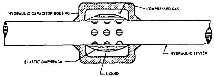 Figure 4-65.-Schematic of experimental isolation type hydraulic capacitor.
the most effective method of suppressing transverse acoustic modes of combustion instability. This has been demonstrated in both full-scale thrust chamber and small-scale models, operating with various propellant combinations. These baffles are usually designed to be secured to the injector face as shown in figure 4-40. Adequate cooling means should be provided to keep the baffles from burnout. The depth or height of the baffles is a function of the distance of the combustion-flame front from the injector face. Experimental evaluations should be conducted to support the design and development effort. 3. Chamber divergent wall gap.-It was found experimentally that leaving blank an annular portion of the propellant injection area adjacent to the combustion chamber wall, as shown in figure 4-66, improved the capability of the combustion chamber to recover from triggered instabilities. It was further determined that by filling this "wall gap" with a contoured filler block, "dynamic stability" could be drastically improved in most cases. The exact shape of the contour is critical, and experimental evaluations are required to determine the most effective design configuration. 4. Acoustic chamber liners.-The feasibility of using resonant and nonresonant acoustic suppressing liners on the combination chamber walls has been demonstrated in turbojet engine applications. In this case the principle of suppression is similar to the use of patches of acoustic tile to reduce the sound level in a room, whereby the energy absorbed from the mode will reduce its amplitude. Figure shows a typical arrangement. The combined area of the suppressor openings must be of the order of from 3
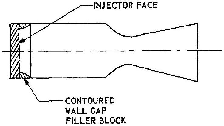 Figure 4-66.-Combustion chamber divergent wall gap.
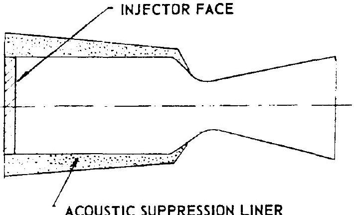 Figure 4-67.-Combustion chamber acoustic liner.
to 4 percent of the total chamber wall surface area. Furthermore, the suppressor thickness should be maximum in the area of maximum pressure variation; i.e., near the injector face.
Rating Stability
It is desireable to establish the combustion stability level of a particular engine system without an excessive number of tests. This can be accomplished by perturbing a normally stable system by suitable means until instability is initiated. The relative stability of various systems is then judged as a function of the magnitude of perturbation needed to reduce the instability. The larger the perturbation, the more stable the system. The perturbation can be introduced in either the propellant feed system or in the combustion chamber. Several effective methods exist for inducing different types of instability.
Feed System Perturbations
Perturbation in the propellant feed system to induce disturbances in the chamber of the lowfrequency hydrodynamic type, can be introduced by- (1) Explosive charges in the fuel feed system (2) Single-stroke positive displacement pistons (3) Oscillating pistons
gure 4-67.-Combustion chamber acoustic liner.
Figure 467.-Combustion chamber acousticiner.
4 percent of the total chamber wall surface a. Furthermore, the suppressor thickness variation; i.e., near the injector face.
PM
ting Stability
It is desireable to establish the combustion ability level of a particular engine system thout an excessive number of tests. This can accomplished by perturbing a normally stable stem by suitable means until instability is tiated. The relative stability of various sysms is then judged as a function of the magnide of perturbation needed to reduce the instality. in
![]() roduced in either the propellant feed system in the combustion chamber. Several effective methods exist for inducing different types of
instability.
roduced in either the propellant feed system in the combustion chamber. Several effective methods exist for inducing different types of
instability.
 (a.) PURECTED EXPLOSIVE
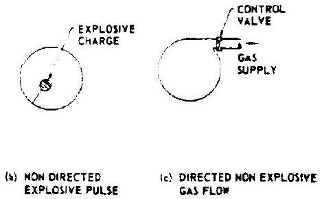
Figure 4-68.-Combustion chamber perturbation methods.
Combustion Chamber Disturbances
The introduction of disturbance in the chamber proper offers a simpler method of inducing instability. Transverse acoustic modes have been initiated most successfully by the following methods:
- Directed explosive pulses.-The directed explosive pulse method of inducing instability, as shown in figure 4-68a, uses a high explosive charge mounted in an external fixture which is attached to the combustion chamber in such a way that the gas pulse resulting from the detonation enters the chamber with any desired orientation.
- Nondirected explosive pulses.-The closest simulation of localized random detonations which can occur in a chamber during normal operation due to accumulation of unburned propellants is achieved by the nondirectional explosive pulse method as shown in figure 4-68b. An explosive is placed into a thin-walled Micarta shell which is designed to be mounted at any desired position in the chamber.
- Directed nonexplosive gas flows.-In this method, as shown in figure 4-68c, a flow of gas from a regulated high-pressure source is controlled by a fast-acting valve. This valve is placed as near to the chamber as possible. This method additionally permits a better definition of the parameters associated with the disturbance.
 a n
a n

 varross s